Tunnelling
Many corporate networks are shielded from the outside world by firewall devices or by the simple expedient of running the network on private IP addresses that are not routed over the global Internet. Either or both of these measures may be present at both ends of a VPN, preventing external packets from reaching systems connected to the LAN. However the purpose of a VPN is to allow a remote host or site to become part of the LAN, and so the security measures used to guard against intrusion from the Internet must be selectively circumvented to allow the VPN to work. Yet another reason for tunnelling is an encryption of the original packet: if all its fields including the IP header ones are encrypted then routers just can’t do their job.
The solution is to use tunnelling, in which a packet destined for the remote site is placed inside another IP packet with globally routable source and destination addresses. A VPN consists of two stations, known as the tunnel endpoints, that perform the necessary operations. When a tunnelled packet is received by the destination end point, the headers concerned with the tunnel are stripped away to reveal the original packet that is delivered to the final destination.
All tunnelling involves encapsulation of the original packet or frame before it is released onto the Internet. Three protocols are involved in the process:
- the passenger protocol is the original packet and will be either a network layer protocol (IP, IPX, AppleTalk® etc.) or a PPP frame
- the encapsulating protocol is the transport-layer protocol that is wrapped around the original data
- the carrier protocol is used by the network carrying the tunnelled packet and must be IP if tunnelling is to take place over the Internet.
There are two types of tunnelling, distinguished by the nature of the passenger protocol. In a Layer III tunnel, the passenger protocol is a network-layer protocol such as IP or AppleTalk®. In Layer II tunnelling it is a data-link protocol (usually PPP).
Layer III Tunnelling
An IP datagram is encapsulated and this takes place before any Layer II components (headers and trailers) have been applied. This type of tunnelling is often associated with inter-site VPNs in which the two tunnel endpoints are both perimeter routers.
There are a number of types of Layer III tunnelling that are distinguished by the encapsulating protocol employed. This guide concerns itself with the two commonest types: GRE (Generic Routing Encapsulation) tunnels and IPSec tunnelling mode, which is covered in Section 6. The more obscure protocols are too specialised to warrant further mention.
GRE Tunnelling
This is a protocol developed by Cisco® that can encapsulate a wide variety of packet types within IP tunnels [6]. It is a transport (Layer IV) protocol operating at the same level as TCP, UDP and ICMP (Internet Control Message Protocol) and is assigned IP protocol number 47. When employed natively, GRE is suited to static tunnels that remain configured on the two tunnel endpoints, often Internet-connected routers, regardless of whether data is flowing at any given instant. Several other tunnelling technologies also use enhanced versions of GRE as the encapsulating protocol, including the Layer II tunnelling technology PPTP (Point-to-Point Tunnelling Protocol ) that is discussed in Section 5.2.4.
The encapsulation process is illustrated in Figure 3 and involves the prepending of a GRE header and a fresh IP header to the original datagram.

Figure 3
Usually, the destination of the original packet is not deliverable over the Internet because it is an address from a private IP range. The tunnelling process creates a new IP header with a destination address that is the remote end-point of the tunnel and that is reachable over the Internet. When the peer receives this packet, it is decapsulated (the IP and GRE headers are removed), thereby exposing the original IP header. The reconstituted datagram is then routed within the internal network and delivered to the specified station.
The GRE protocol header supports checksums, keys and sequencing, all of which are optional.
- The checksum field contains the IP (one’s complement) checksum sum of all the 16-bit words in the GRE header and the payload packet.
- The key field contains a four-octet number that was inserted by the encapsulator. The key can identify an individual traffic flow within a tunnel should this facility be required. It should never be used as a form of weak security as simple packet sniffing will reveal its value.
- The intended use of the four-byte sequence field is to provide unreliable but in-order delivery. If a key is used, the sequence number is specific to the traffic flow identified by the key field.
As a simple example of a GRE Layer III tunnel in action, consider two colleges each with connections to JANET.

One of the colleges operates a student records database server on their privately numbered administrative LAN and wishes to allow the other college access to the server. For security reasons, it is decided not to create a network address translation mapping to the server’s IP address within the border router. Instead, a GRE tunnel is established between the two sites by configuring logical ‘tunnel’ interfaces on each of the routers and then routing traffic to the peer site’s privately numbered network via the tunnel interface. Elements of the configuration of the routers are shown on the following page.
Traffic destined for the internal (privately-addressed) network at the far end of the tunnel is statically routed via the tunnel interface on both routers. Any packets leaving a tunnel interface have a GRE and a new IP header added. The source and destination fields of the outermost IP header are filled with the IP addresses of the serial interfaces of the two routers. The tunnelled packet then leaves the source router via its serial interface and is routed over the Internet to the peer router.

Layer II Tunnelling
In Layer II tunnelling, the encapsulation process takes place after the data-link header and trailer have been applied. The corollary of this is that the Layer II tunnelling process cannot be applied selectively (deciding whether to tunnel a packet based on, for example, its source or destination IP addresses). A station with active Layer II tunnelling blindly dispatches all outbound traffic to its tunnelling peer.
There are three Layer II tunnelling protocols, the most recent of which, L2TP (Layer II Tunnelling Protocol), is a synthesis of the two earlier protocols, L2F (Layer II Forwarding) and PPTP. This document discusses L2TP and PPTP.
There are two possible modes of Layer II tunnelling. Compulsory tunnelling means that the tunnel is always active while voluntary tunnelling allows the user to dial the ISP and then decide whether to initiate a Layer II tunnel.
Compulsory Tunnelling
This type of tunnelling requires the active participation of the ISP. The client station forms a connection to the LAC(L2TP Access Concentrator) via a media that supports PPP such as a dial-up modem or an ADSL connection. The LAC is operated by the ISP and would most often be a dial-up server of some description. Upon receipt of frames from the client station, the LAC securely tunnels these to the LNS (L2TP Network Server) without any required knowledge or participation by the client. The LNS would be, for example, an Internet-connected router residing at a company’s offices with the client station representing a teleworking employee. (Figure 4).
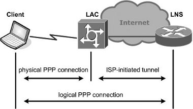
Figure 4. Compulsory tunnelling.
Because every frame is dispatched via the tunnel, then from the perspective of the client station there exists a direct PPP connection between itself and the remote tunnel endpoint, the intervening infrastructure being completely transparent. This arrangement can be highly advantageous as it allows organisations to provide the benefits of a dial-up service to their remote employees without incurring the support burden of actually operating the dial-up aspect of the service. It does, however, require a special ISP service.
Voluntary Tunnelling
If it is deemed preferable for the client station to initiate the tunnelling process, the dial-up ISP need play no role other than providing normal Internet connectivity.
The encapsulation process is similar to the compulsory tunnelling scenario except that the client station assumes the tunnelling role that would otherwise be performed by the ISP’s dial-up server hardware. The advantage of voluntary tunnelling is that the client can obtain general Internet connectivity by dialling the ISP and need only initiate the tunnel when it is needed. (Figure 5)

Figure 5. Voluntary tunnelling.
Layer II Tunnelling Protocol (L2TP)
This is the most recent member of the family of tunnelling protocols for Layer II frames. L2TP is not limited to IP networks, being able to tunnel non-IP protocols such as AppleTalk® and IPX over non-IP networks such as Frame Relay or ATM (Figure 6).
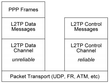
Figure 6. Layer II Tunnelling Protocol (L2TP).
L2TP utilises two types of messages, control messages and data messages [7]. Control messages are used in the establishment, maintenance and clearing of tunnels and calls. Data messages are used to encapsulate PPP frames being carried over the tunnel. Control messages utilise a reliable channel within L2TP to guarantee delivery. Data messages are not retransmitted by L2TP when packet loss occurs. Sequence numbers (within the L2TP header) are required for control messages so that their delivery is guaranteed. L2TP messages include a Next-Received field and a Next-Sent field, which are comparable to TCP’s Acknowledgement Number field and Sequence Number field respectively. Delivery of control messages has to be managed in-band by L2TP itself because the carrier network may not offer reliable delivery. These messages take the form of Attribute-Value Pairs.
Security
No specific allowance is made within the L2TP specification for security. However, since L2TP can run over IP, it is possible to deploy transport mode IPSec to provide security services.
L2TP Over IP
L2TP data tunnelling begins with a PPP payload. The PPP frame is encapsulated with a L2TP header. The encapsulating protocol, UDP, is applied. L2TP uses UDP port 1701 for both the source and destination port. Finally, the outermost IP header can be applied (Figure 7).
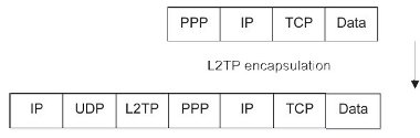
Figure 7. L2TP over IP.
Availability
Because L2TP is a synthesis of Cisco®’s earlier L2F and Microsoft®’s PPTP, both these vendors offer L2TP natively with their operating systems. Although Cisco® routers support L2TP as part of the standard IOS (Internetworking Operating System), most users will wish to deploy the new security features. IPSec is only provided as part of the 3DES Firewall feature set, which is a chargeable option. Microsoft® provides a full implementation of L2TP with Windows® 2000/XP and later.
Point-to-Point Tunnelling Protocol (PPTP)
This protocol was developed jointly by an alliance of vendors. In contrast to L2TP, it can only tunnel PPP frames over an IP carrier network [8]. Two connections are required for a PPTP tunnel; a data tunnel and a separate control connection operating on TCP port 1723. After the two peers have established a tunnel, they send PPTP control-connection packets back and forth to maintain the connection. These control-connection packets consist of PPTP Echo-Request and PPTP Echo-Reply messages. The data connection utilises GRE as the transport protocol and it is this fact that restricts the carrier protocol to IP. The separate control channel is required because GRE lacks the functionality to set up a session. Secure authentication is provided by means of MS-CHAP (Microsoft® Challenge Handshake Authentication Protocol) and the data stream may be secured using MPPE (Microsoft® Point-to-Point Encryption ) that uses RC4 (Rivest’s Cipher 4, also known as Ron’s Code 4), a stream cipher, to encrypt the PPP datagrams.
Security concerns have dogged PPTP since its inception. It is the author’s opinion that PPTP is inherently insecure because there are too many unauthenticated control packets that are readily spoofed. The availability of L2TP secured with IPSec has now rendered PPTP obsolete.


