IP security: overview and architecture
There are no security provisions within the IP standard that guarantee that received packets:
- originate from the claimed sender
- have not been inspected or modified by a third party during transmission
- have not been replayed from earlier transmissions.
Most of the traffic sent over JANET or the Internet is not of a nature to warrant concerns about these matters, or alternative application-level methods are available to verify the origin or encrypt transmissions. For example, HTTPS is a secure version of HTTP available for transmitting sensitive data (such as credit card details) over the World Wide Web. HTTPS is based on SSL – see Section 8.
A VPN, however, will cause internal data, which is assumed to be sensitive, to be transmitted over an external shared network. Furthermore, users will expect access to all of the available local network services and so a solution that relies upon individual application security features will not be suitable. This chapter examines the security extensions to the IP standard, IPSec, that provide a framework within which encryption and authentication algorithms may be applied to IP packets.
IPSec is a suite of three transport-level protocols used for authenticating the origin and content of IP packets and, optionally, for the encryption of their data payload [9]. Two of the protocols, AH (Authentication Header) [10] and ESP (Encapsulating Security Payload) [11], provide authentication, comprising proof of data source, data integrity and anti-replay protection. Additionally, ESP (but not AH) provides data encryption. The third IPSec protocol, IKE (Internet Key Exchange ), is a complex hybrid protocol used for the peer authentication and key exchange processes that necessarily precede the services provided by AH and ESP.
The IPSec protocols do not define which algorithms should be used for the computations involved in encryption or in generating digital signatures. This renders the protocol definitions completely generic, meaning they can accommodate developments such as new cryptographic techniques as they become available. The algorithms to be used are specified separately as part of the overall security policy configured at each of the peer stations. The initial IKE negotiations allow the peers to agree on the particular combination of protocols and algorithms to be used for all subsequent IPSec processing.
IPSec Security Associations (SAs)
These are fundamental to the operation of IPSec. Prior to the transmission of protected datagrams, the two peer stations must reach an agreement on how the conversations between them should be processed by IPSec. They agree upon the protocol, the transform, the keys and the key lifetime. This ‘contract’ between a pair of IPSec peers is the Security Association (SA).
The SAs are simplex (i.e., unidirectional) in nature. If two stations, X and Y, are communicating securely then each will maintain two SAs, one for outbound and one for inbound traffic. It should be apparent therefore that (SAout) x would share the same cryptographic parameters with (SAin) y.
The defining characteristics of an active SA are the result of a negotiation between two IPSec peers. Each peer must be configured in advance with the selection of protocols and transforms it is willing to accept from or is able to offer to a peer. Suppose station X is configured to offer ESP with the DES encryption and the MD5 integrity algorithms and to offer AH with the MD5 algorithm, while station Y is only configured to use AH with the MD5 algorithm; the SA negotiation between these two peers would then result in each agreeing to protect their conversations with the AH protocol and the MD5 algorithm. Because station Y has not been configured to use ESP then it will not form SAs employing this protocol. These predefined policies are known as the Security Policy Database (SPD). Gross failures in IPSec processing are often caused by a lack of any common protocol or algorithm in the SPDs of two peers. Thus the initial IKE main mode negotiations fail to reach an agreement and no SAs can be established.
Security Parameter Index (SPI)
When an IPSec-protected datagram is received, it is clearly important that the station to which the packet has been sent is able to determine which of its SAs it should use when processing the secured packet. The SPI is an arbitrary 32-bit value that, together with the destination IP address of the outer IP header and the protocol (AH or ESP), uniquely identifies the SA to the receiving station. The sending station includes an SPI with each packet it dispatches identifying the receiving peer’s inbound SA. If the SA cannot be recognised, the receiving station drops the packet without attempting any further processing. In database terminology, the <SPI, destination IP address, protocol> tuple may be regarded as the primary key of the receiving station’s SA Database. (A tuple is an ordered set of values (often separated by commas) and is analogous to a record in a non-relational database.)
Sequence Numbers
The sender dispatches this unique and monotonically increasing 32-bit unsigned integer with each secured packet to guard against replay attacks. The receiving station checks this field to determine whether the packet is a duplicate of one that has already been received. The sequence number is incremented by one for each packet processed through a given SA. The SAs are usually renegotiated before this number overflows.
Sequence numbers are required to protect against a replay attack in which an attacker intercepts and stores packets emanating from the sending station. The attacker then floods the receiving station by repeatedly resending these intercepted packets. This is a form of denial-of-service attack.
Management of SAs
The management of SAs concerns their creation and deletion. Creating security associations is a two-stage process in which parameters are first negotiated with the IPSec peer and the SA Database is then updated with the new SA. It is mandatory for all implementations of IPSec to support manual keying in which all the necessary parameters are agreed offline (e.g. by means of a telephone conversation). Manually constructed SAs never expire and the processes involved in their creation are cumbersome and insecure. It is preferable, therefore, that a key management protocol such as IKE is deployed to create the SAs. Various triggers cause an SA to be deleted. These comprise:
- expiration of the key lifetime
- compromised keys
- the number of bytes processed through the SA reaching a threshold
- the security peer requesting that the SA is torn down.
In order to avoid unnecessary interruptions, a new replacement SA will be negotiated a short time before the existing one is deleted. Once this new SA has been fully established, it will be used immediately and the older one will be deleted shortly thereafter.
IPSec Modes
The principal function of IPSec is to provide a standards-based framework defining how IP packets may be protected during their transmission. There is also an important ancillary function whereby IPSec provides the functionality to tunnel the packets it is protecting. Prevailing circumstances determine whether it is necessary to tunnel the protected packets, and so IPSec may be operated in two different modes wherein the tunnelling functionality is either active or suppressed. The difference between the two modes concerns the location of the IPSec header within the original IP packet. This in turn affects the degree of protection that IPSec affords.
Tunnel Mode
When the destination of the original, unsecured packet is not the same as the remote security endpoint, IPSec must operate in tunnel mode. The IPSec header and a new IP header are prepended to the original packet as shown.
| IP | ESP/AH | IP | TCP | Data |
The corollary is that in tunnel mode, protection is afforded to the entire IP packet and not just its payload between the tunnel end points. Figure 8 depicts a typical scenario where IPSec would be required to operate in tunnel mode.

Figure 8. A typical scenario where IPSec would be required to operate in tunnel mode.
The two communicating stations are connected to privately numbered networks and cannot therefore communicate directly. The Internet-connected routers act as the security endpoints. Packets are received from the sending station and encapsulated by the source router. The new outer IP header has the Internet-valid router addresses asthe source and destination. When the tunnelled packets arrive at the destination router, the outer IP header is removed and the original IP packet is regenerated as a result of the IPSec processing. This packet is then transformed into an Ethernet frame and delivered to the local destination in the usual manner.
Transport Mode
Here, the IPSec header (AH or ESP) is inserted between the original packet’s network and transport headers as shown below.
| IP | ESP/AH | TCP | Data |
Consequently, the IP payload is protected in transport mode but the header is not. Transport mode is suitable under two circumstances.
Firstly, if the two stations participating in the underlying communication are also the IPSec peers then there is clearly no need to tunnel the secured packets. This will usually be the case if the two stations are able to communicate directly because they are operating on Internet-valid IP addresses.
Secondly, circumstances may dictate that while IPSec is used to provide security services, an alternative tunnelling technology should be deployed. For instance, IPSec may be used to secure packets that have been routed through a tunnel interface on a Cisco® router. The Layer III tunnel is here accomplished by means of some other (normally GRE) encapsulation and it is therefore appropriate for IPSec to operate in transport mode, as an outer IP header has already been provided. This may seem to be a contrived method of achieving the same object as tunnel-mode IPSec, but there are cases when such techniques are required and a full example is discussed in Section 7.
IPSec Protocols
The two IPSec protocols, AH and ESP, both operate at the same transport layer of the OSI model as the more familiar protocols such as TCP and UDP. In order to protect a packet with IPSec, that packet must be encapsulated with one of these two protocols.
Authentication Header
Because AH provides only authentication and not confidentiality it is a fairly simple protocol, creating just a header and no trailer. The header contains the SPI, the sequence number and the authentication data (Figure 9).
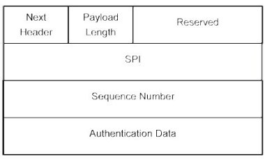
Figure 9. Authentication Header.
This latter field contains the Integrity Check Value, which offers assurance that the packet has not been altered during its transmission. The SA specifies the algorithm used to calculate this value. A family of suitable algorithms is the MAC such as MD5 or SHA-1. The Next Header is an 8-bit field indicating what protocol follows the AH header. When IPSec is running in tunnel mode, the value of this field will be 4 (IP-in-IP). In transport mode, it will be the upper-layer protocol being protected (usually UDP or TCP).
Encapsulating Security Payload (ESP)
This protocol must be used when data encryption is required. Because it is an IPSec header, ESP provides SPI and sequence numbers whose purposes have been discussed in the preceding section. Padding (to a maximum of 255 bytes) is used by ESP to preserve byte boundaries. If an encryption algorithm is employed that requires the plaintext to be a multiple of some number of bytes (for example the block size of a block cipher), the padding field is used to fill the plaintext to the requisite size. Padding may also be required, irrespective of encryption algorithm requirements, to ensure that the resulting ciphertext terminates on a 4-byte boundary, thereby right-aligning the trailer (Figure 10).
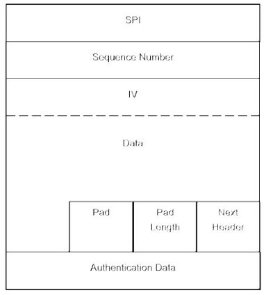
Figure 10. ESP.
Internet Key Exchange (IKE)
A suitable SA must exist before packets can be secured using AH or ESP. The third member of the IPSec family of protocols is IKE and it is used for peer authentication, negotiation of keys and the dynamic construction of SAs. Although the fine details of IKE are complex and lie outside the scope of this guide, an understanding of the methods used in the establishment of IPSec SAs is invaluable when troubleshooting.
A hybrid protocol, IKE [12] combines parts of the Oakley key determination protocol and the SKEME (Security Key Exchange Mechanism), both key exchange protocols, with the ISAKMP (Internet Security Association Key Management Protocol). The latter defines a framework for peer authentication, key exchange and SA management over an IP network and operates on UDP port 500.
An IKE negotiation consists of two phases in which an IKE SA is first established (Phase 1) to provide a secure communications channel through which SAs for other protocols (e.g. IPSec) may be constructed (Phase 2). There are two mutually exclusive methods by which a Phase 1 IKE negotiation may proceed; main mode or aggressive mode. The phase 2 negotiations are conducted using a quick mode exchange.
Main Mode
A main mode exchange uses six messages in three round trips. In the first exchange, the peers negotiate the parameters of the IKE SA and how the remaining exchanges will be accomplished. The next two exchanges are used for the exchange of the Diffie-Hellman keying material. The final pair of main mode messages is used for authenticating the peers’ identities. This last exchange is encrypted using the previously negotiated key, thereby protecting the identities of the peers from eavesdroppers.
Aggressive Mode
An aggressive mode exchange accomplishes the same things as main mode, but using only half the number of messages by embedding some of the messages within others. Consequently, the negotiating abilities of aggressive mode are limited and peer identities are not concealed.
Quick Mode
After an IKE SA has been established by means of a Phase 1 exchange (in either main or aggressive mode), it can be used to construct the IPSec SAs using a Phase 2 exchange in quick mode. With the exception of the ISAKMP header, all quick mode exchanges are encrypted and authenticated.
The security peers exchange the IPSec keys (one for each SA) as part of the quick mode exchange. This is done by first exchanging pseudo-random nonces (a nonce is a parameter that varies with time) that are hashed with the IKE shared secret. The resulting unique IPSec keys do not have the property of Perfect Forward Security (PFS) because they are all derived from the same IKE shared secret. With PFS, if one key is compromised, previous and subsequent keys remain secure because subsequent keys are not derived from previous keys. An additional Diffie-Hellman exchange is performed with each quick mode exchange if PFS is specified in the IPSec policy. Because each Diffie-Hellman exchange requires large exponentiations, PFS will exact a performance cost. The shared secret derived from a quick mode Diffie-Hellman exchange is used to generate IPSec keys that have no ‘memory’ of their predecessors.
IPSec Domain of Interpretation (DOI)
The IKE protocol defines how security parameters are negotiated and shared keys are established for other protocols. It does not define what to negotiate. That is the function of a Domain of Interpretation (DOI) document that defines, amongst other things, the attributes that IKE negotiates in quick mode. There currently exist DOI documents for IPSec and for the routing protocols RIP (Routing Information Protocol ) and OSPF (Open Shortest Path First ).
In summary, IKE may be regarded as an authenticated Diffie-Hellman exchange with ISAKMP providing the necessary network framework.


